Introduction
Choosing a reducer pipe fitting is not just a matter of matching two pipe diameters; it directly affects flow behavior, pressure loss, vibration, and the service life of the system. This article explains the main reducer types, where each is typically used, and the practical sizing factors that influence performance, including fluid flow, layout constraints, and installation conditions. By the end, readers will be able to compare common options more confidently and select a fitting size that supports efficient operation, reliable connections, and fewer long-term maintenance problems.
Why reducer pipe fitting selection affects system performance
The specification of a reducer pipe fitting extends far beyond simply connecting two pipes of different diameters. As a critical transition point within a pressurized piping network, the reducer dictates fluid dynamics, structural integrity, and overall system efficiency.
Engineers must evaluate these components not just as static joints, but as active contributors to the hydraulic profile of the system. A poorly selected reducer can compromise flow rates, increase energy consumption, and introduce mechanical stress that shortens the lifespan of adjacent equipment.
How reducer fittings influence pressure drop
Every change in pipe diameter introduces a localized disturbance in the fluid stream. A reducer pipe fitting alters the cross-sectional area, which inversely affects fluid velocity according to the principle of continuity. This acceleration or deceleration generates a pressure drop determined by the fitting’s resistance coefficient (K-factor).
For standard concentric reducers, K-factors typically range from 0.05 to 0.5, depending on the angle of the reduction cone and the ratio of the connecting diameters. Failing to account for this pressure drop in highly calibrated systems can lead to inadequate downstream pressure. For instance, an abrupt transition that increases fluid velocity from 5 feet per second (fps) to 12 fps can exponentially increase frictional losses, forcing centrifugal pumps to operate outside their Best Efficiency Point (BEP) and driving up electrical consumption.
Where sizing errors create reliability problems
Incorrect sizing or geometry selection directly correlates with mechanical and hydraulic failures. When fluid velocity increases too rapidly through an excessively steep reduction, it can induce cavitation, particularly if the localized pressure drops below the fluid’s vapor pressure. In liquid systems, collapsing vapor bubbles can erode standard carbon steel fittings rapidly, sometimes reducing wall thickness by millimeters per year.
Furthermore, improper use of a concentric reducer pipe fitting at a pump suction line is a notorious source of reliability issues. Because the top of a concentric reducer slopes downward, it can trap air or vapor pockets. This trapped gas can reduce the Net Positive Suction Head Available (NPSHa) by as much as 1.5 to 3.0 feet. When this air is ingested by the pump, it induces severe vibration, leading to premature mechanical seal degradation and bearing failure.
Reducer pipe fitting types and specifications
Specifying the correct reducer requires a thorough understanding of the available geometries, end connections, and material constraints. The physical shape of the fitting determines how fluid transitions between pipe sizes, while the material and schedule dictate the fitting’s ability to withstand internal pressures and corrosive environments.
Concentric vs eccentric reducer fittings
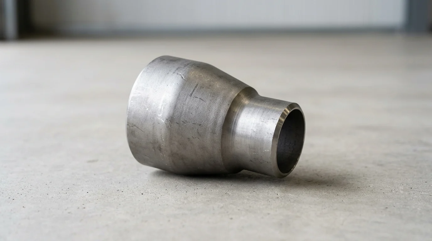
The primary geometric distinction in reducer pipe fittings is between concentric and eccentric designs. A concentric reducer features a symmetrical, cone-shaped profile where the centerlines of both the large and small ends align perfectly. This design is standard for vertical piping runs and horizontal lines where air pooling is not a concern, as it provides a uniform transition that minimizes flow turbulence.
An eccentric reducer, conversely, is manufactured with one flat side, meaning the centerlines are offset. This flat side is typically oriented upward (flat-on-top) in horizontal pump suction lines to prevent the accumulation of air pockets. In gravity-fed drainage systems, the flat side is often oriented downward (flat-on-bottom) to ensure complete fluid drainage and prevent sediment buildup.
End types, schedules, and material grades
Reducer pipe fittings are manufactured with various end types to suit different installation methods. Butt weld ends (governed by ASME B16.9) are the most common for high-pressure industrial applications, offering seamless flow and high radiographic integrity. Socket weld (ASME B16.11) and threaded ends are generally reserved for smaller pipe sizes, typically under 2 inches in nominal diameter.
Matching the pipe schedule (wall thickness) is critical. A system transitioning from a Nominal Pipe Size (NPS) 8 to NPS 6 must maintain the required pressure rating across the fitting. If the line is Schedule 40, the reducer must also meet Schedule 40 parameters, which translates to a wall thickness of 0.322 inches for the 8-inch side and 0.280 inches for the 6-inch side. Material grades must also align with the piping system; common specifications include ASTM A234 WPB for standard carbon steel and ASTM A403 WP316/316L for corrosive or high-temperature stainless steel applications.
Comparison table for reducer fitting options
The following table highlights the operational differences and standard deployment scenarios for the two primary reducer geometries.
| Feature / Parameter | Concentric Reducer | Eccentric Reducer |
|---|---|---|
| Geometry | Symmetrical cone, aligned centerlines | Offset centerlines, one flat side |
| Primary Orientation | Vertical piping, non-critical horizontal runs | Horizontal pump suction, drainage lines |
| Air Pocket Risk | High (in horizontal liquid lines) | Low (when installed flat-on-top) |
| Turbulence Factor | Lower (uniform fluid transition) | Slightly higher (asymmetrical flow path) |
| Manufacturing Cost | Baseline | Typically 10-20% higher than concentric |
How to choose reducer pipe fitting size
Selecting the precise size for a reducer pipe fitting requires more than knowing the starting and ending pipe diameters. The sizing process must integrate dimensional standards with the hydraulic demands of the specific process system to ensure safety and operational longevity.
Dimensions and specifications that govern sizing
The physical footprint of a reducer pipe fitting is governed by strict dimensional standards to ensure interchangeability. For butt-welding fittings, ASME B16.9 dictates the exact outside diameters (OD) and the end-to-end length of the fitting. For example, a standard transition from NPS 6 to NPS 4 involves an OD change from 6.625 inches to 4.500 inches.
The overall length of the fitting is fixed by the standard to allow piping designers to calculate spool dimensions accurately. According to ASME B16.9, an NPS 6 x 4 concentric or eccentric reducer has a standardized end-to-end length of 5.50 inches. Adhering to these published dimensions is mandatory for pre-fabrication, ensuring that the fitting aligns precisely with adjacent flanges, valves, and straight pipe sections without requiring on-site modifications.
How to match fitting size to system conditions
Matching the fitting size to system conditions requires hydraulic calculations to ensure fluid velocities remain within acceptable thresholds. Industry best practices generally limit water velocity in carbon steel pipes to below 15 fps to prevent accelerated erosion-corrosion. If a reduction in pipe size forces the velocity above this limit, the system may require a more gradual reduction or a change in material specification.
Additionally, the sizing must account for the specific gravity and viscosity of the medium. Highly viscous fluids, such as heavy crude oils or syrups, experience amplified friction losses through a reducer. In such cases, stepping down the pipe size over a longer run using a two-step reduction (e.g., NPS 10 to NPS 8, then NPS 8 to NPS 6) rather than a drastic one-step reduction (NPS 10 to NPS 6) can preserve vital pump head pressure.
Step-by-step reducer selection process
To ensure accurate procurement and installation, engineers should follow a structured sizing process. First, determine the nominal pipe sizes and exact outside diameters of the mating pipes. Second, calculate the required wall thickness (schedule) based on the system’s maximum allowable working pressure (MAWP) and design temperature.
Third, select the geometry (concentric vs. eccentric) based on the orientation of the pipe run and the proximity to sensitive equipment like pumps or compressors. Finally, cross-reference the selected dimensions against standard manufacturing lengths.
| Nominal Size Reduction (NPS) | Large End OD (inches) | Small End OD (inches) | Standard Length (ASME B16.9) |
|---|---|---|---|
| 4 x 2 | 4.500 | 2.375 | 4.00 inches |
| 6 x 4 | 6.625 | 4.500 | 5.50 inches |
| 8 x 6 | 8.625 | 6.625 | 6.00 inches |
| 10 x 8 | 10.750 | 8.625 | 7.00 inches |
Standards, quality control, and procurement checks
Procuring a reducer pipe fitting involves stringent quality control and verification against international standards. Because these fittings often operate under high pressure and extreme temperatures, non-compliant components pose significant safety risks and can lead to catastrophic facility downtime.
Codes and standards for reducer pipe fittings
The manufacturing, testing, and rating of reducer fittings are governed by rigorous industrial codes. ASME B16.9 covers the overall dimensions and tolerances for factory-made wrought butt-welding fittings, while ASTM material standards dictate the chemical and mechanical properties. For instance, ASTM A234 is the standard specification for piping fittings of wrought carbon steel and alloy steel for moderate and high-temperature service.
Under these codes, a fitting must be capable of withstanding the same internal pressure as a straight seamless pipe of equivalent material and wall thickness. An ASTM A234 WPB reducer pipe fitting, for example, must demonstrate a minimum yield strength of 35,000 psi and a tensile strength ranging between 60,000 and 85,000 psi to ensure it will not fail under rated operational loads.
How to assess mill test reports and tolerances
Quality assurance relies heavily on the evaluation of Mill Test Reports (MTRs). A valid MTR provides traceability from the raw material heat to the finished fitting. Procurement teams must verify that the chemical composition listed on the MTR aligns with the standard; for carbon steel WPB grades, the maximum carbon content is strictly capped at 0.30% to guarantee weldability.
Dimensional tolerances must also be verified upon receipt. For smaller reducers (NPS 8 and under), ASME B16.9 permits an outside diameter tolerance of +1.6 mm / -0.8 mm (+0.06 / -0.03 inches) at the bevel. Wall thickness cannot fall below 87.5% of the nominal specified thickness. Fittings that fall outside these tolerances can cause misalignment during fit-up, resulting in defective welds and failed non-destructive testing (NDT).
Commercial factors in reducer fitting sourcing
Beyond technical specifications, commercial factors play a significant role in sourcing reducer pipe fittings. Availability and lead times vary drastically based on material and size. Standard carbon steel reducers up to NPS 24 are typically available off-the-shelf or with short 2-to-4-week lead times.
Conversely, fittings required in exotic alloys—such as Duplex stainless steel, Hastelloy, or Inconel—or those exceeding NPS 36 often require bespoke forging runs. These specialized components can carry lead times of 12 to 20 weeks and may be subject to Minimum Order Quantities (MOQs). Buyers must balance the upfront cost of expedited manufacturing against the operational cost of project delays, making early procurement of non-standard reducers a critical project management priority.
Final framework for selecting the right reducer pipe fitting
Finalizing the specification for a reducer pipe fitting requires a holistic approach that balances process engineering requirements with procurement realities. Establishing a clear decision framework ensures that the selected fitting delivers both immediate functionality and long-term reliability.
Decision framework for fitting selection
An effective decision framework for fitting selection prioritizes safety and process requirements above all else. The first tier of decision-making involves fluid dynamics: determining the required flow rate, allowable pressure drop, and the necessity of preventing air entrainment, which dictates the choice between concentric and eccentric geometries.
The second tier addresses metallurgical and structural integrity. Engineers must select a material grade and schedule that exceeds the system’s MAWP and provides adequate corrosion allowance for the projected lifecycle. Only after these technical baseline requirements are met should the framework shift to the third tier: evaluating connection types, dimensional standards, and overall footprint integration within the piping isometric drawings.
Final criteria for balancing compliance and availability
The final criteria often require balancing strict engineering compliance with supply chain availability. While a bespoke, multi-step reduction fitting might offer the absolute optimal hydraulic profile, the extended lead time and high cost may not be justifiable. In such cases, designers frequently standardize on readily available one-step or two-step standard reducers.
By limiting specifications to common sizes and standard reduction ratios, facilities can reduce their replacement parts inventory costs by as much as 15% to 25%.
Key Takeaways
- The most important conclusions and rationale for reducer pipe fitting
- Specs, compliance, and risk checks worth validating before you commit
- Practical next steps and caveats readers can apply immediately
Frequently Asked Questions
What is a reducer pipe fitting used for?
It connects two different pipe sizes while controlling flow transition. In pressurized systems, the right reducer helps limit turbulence, pressure loss, and stress on pumps and valves.
When should I use a concentric reducer instead of an eccentric reducer?
Use a concentric reducer on vertical lines or where air trapping is not a concern. Use an eccentric reducer on horizontal pump suction lines, typically flat-on-top, to avoid vapor pockets.
Why is reducer size selection important for system performance?
A wrong size can raise velocity too quickly, increase pressure drop, and cause cavitation or vibration. Proper sizing helps protect pump efficiency, seals, and nearby piping.
How do I choose the right reducer end type?
For most industrial high-pressure systems, choose butt weld reducers to ASME B16.9. For smaller lines under 2 inches, socket weld or threaded ends may be suitable if allowed by your design code.
What should I confirm before ordering a reducer from nbfh-metal.com?
Check pipe sizes, reducer type, end connection, material grade, and matching schedule. Also confirm application details like pump suction, pressure, temperature, and corrosion exposure to avoid fit or performance issues.
Post time: May-23-2026