Introduction
Reducer pipe fittings do more than join pipes of different diameters—they influence flow velocity, pressure loss, turbulence, and long-term system reliability. This article explains the main reducer types, where each is typically used, and how size selection affects performance in liquid and gas lines. You’ll also learn the practical factors that guide specification, including pipe schedule, end connection, installation orientation, and operating conditions. By the end, you’ll have a clear framework for choosing a reducer that fits the piping layout, supports efficient flow, and avoids common sizing mistakes that can lead to vibration, erosion, or unnecessary pressure drop.
Why the right reducer pipe fitting matters
A reducer pipe fitting serves as a critical transition component within industrial piping systems, facilitating a change in pipe diameter while maintaining fluid containment and structural integrity. Beyond merely connecting two mismatched pipes, these fittings dictate the hydrodynamic efficiency and mechanical reliability of the entire fluid transport network.
Selecting the precise configuration and specification is not a purely geometric exercise. The chosen fitting fundamentally alters the hydraulic profile of the system, requiring engineers to account for fluid velocity, internal pressure dynamics, and mechanical stress distribution to ensure long-term operational stability.
Impact on flow behavior
Altering the cross-sectional area of a pipeline intrinsically modifies the velocity and pressure profile of the transported media. According to the principles of fluid dynamics, decreasing the pipe diameter accelerates the fluid while simultaneously dropping static pressure. For instance, transitioning from an 8-inch to a 6-inch nominal pipe size results in a cross-sectional area reduction that increases fluid velocity by approximately 77%.
If this acceleration is not carefully managed, it can induce severe turbulence, localized pressure drops, and cavitation. In liquid systems operating near their vapor pressure limits, the sudden drop in pressure through a poorly specified reducer can cause vapor bubbles to form and collapse, leading to rapid material erosion and compromised system integrity.
Hidden costs from sizing mistakes
Sizing mistakes in reducer selection often translate directly into compounding operational expenses. When a reducer is undersized or features an excessively abrupt transition angle, the resulting friction and head loss force downstream pumps to work harder to maintain required system flow rates.
Engineering data indicates that improper reducer sizing and the resulting flow restriction can increase a primary centrifugal pump’s energy consumption by 15% to 25% annually due to unnecessary head loss. Over time, this chronic overexertion accelerates pump wear, increases mechanical fatigue on seals and bearings, and drives up both maintenance costs and unplanned downtime. These long-term expenses far outweigh the initial savings of a cheaper, improperly sized fitting.
Reducer pipe fitting types
Industrial piping systems rely on diverse reducer configurations to accommodate specific spatial constraints, fluid characteristics, and mechanical stress requirements. Selecting the appropriate geometry and connection method ensures long-term operational stability and minimizes maintenance liabilities.
Concentric vs eccentric reducers
The primary geometric distinction in reducer pipe fittings lies between concentric and eccentric designs. Concentric reducers feature a symmetrical, cone-like shape where the centerlines of both the larger and smaller ends align perfectly. They are predominantly utilized in vertical piping runs or in systems where fluid accumulation is not a primary concern.
Conversely, eccentric reducers are manufactured with one flat side, intentionally offsetting the centerline. This flat orientation is critical in horizontal piping systems to prevent the entrapment of air or gas pockets, which can severely disrupt flow and damage downstream equipment. When installed on the suction side of a pump, the flat side is typically oriented upwards to ensure a continuous, air-free fluid supply.
| Feature | Concentric Reducer | Eccentric Reducer |
|---|---|---|
| Geometry | Symmetrical, aligned centerlines | Asymmetrical, offset centerline |
| Primary Orientation | Vertical piping | Horizontal piping |
| Air/Gas Entrapment | High risk in horizontal lines | Low risk (when flat side is up) |
| Pump Suction Use | Not recommended | Highly recommended |
Comparing end connection and schedule options
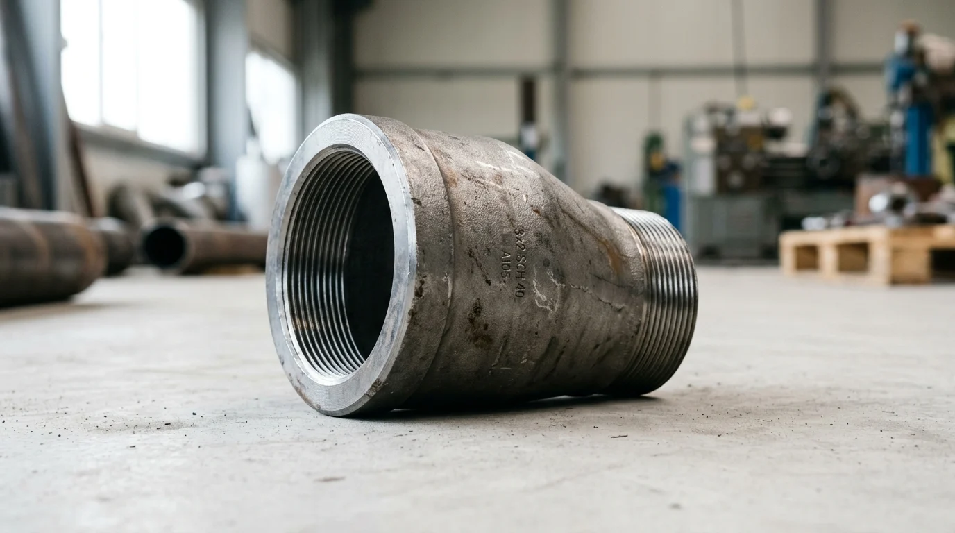
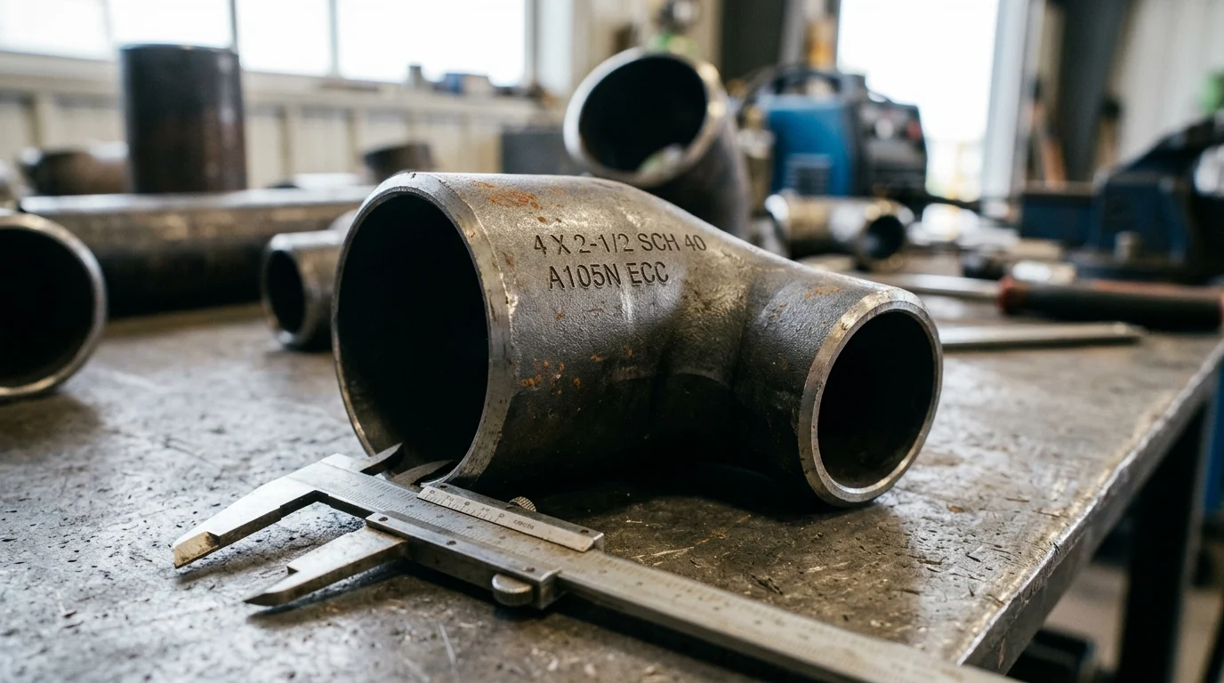
Beyond geometry, reducers are categorized by their end connections and wall thicknesses, commonly referred to as pipe schedules. Butt-weld fittings are the industry standard for high-pressure and large-diameter applications, offering smooth internal flow and high structural integrity across sizes ranging from NPS 1/2 up to NPS 48 and beyond.
Socket-weld and threaded reducers, however, are typically restricted to smaller bore piping—generally limited to NPS 2 (nominal pipe size 2 inches) and smaller. This is due to their susceptibility to crevice corrosion and lower pressure ratings under cyclic loading. Schedule matching is equally vital; a reducer must possess a wall thickness (e.g., Schedule 40, 80, or 160) compatible with the adjacent piping to ensure uniform pressure containment and proper weld alignment.
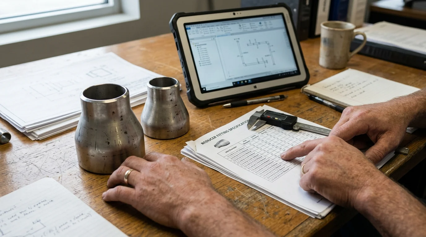
How to select size, wall thickness, and material
Specifying a reducer pipe fitting requires a systematic evaluation of both the dimensional requirements of the piping network and the rigorous demands of the operating environment. A mismatch in either category can lead to catastrophic system failure.
Steps to choose reducer size
The sizing process begins by precisely identifying the outer diameters (OD) of the mating pipes. Engineers must calculate the required volumetric flow rate and establish the maximum allowable pressure drop across the transition zone. Standard industrial sizing nomenclature typically lists the larger diameter first, followed by the smaller diameter (e.g., 6″ x 4″).
When the required diameter reduction spans more than three standard pipe sizes, engineers must evaluate whether a single reducer can handle the transition without exceeding pressure drop thresholds. In high-velocity systems, a massive single-step reduction can cause excessive turbulence. Therefore, a staged reduction using multiple sequential fittings may be required to maintain flow stability and protect downstream instrumentation.
Media, temperature, corrosion, and velocity factors
Material and wall thickness specifications are heavily dictated by the transported media, operating temperature, and internal velocity. For standard water or non-corrosive gas applications, carbon steel is generally sufficient. However, aggressive chemical environments demand higher-grade alloys.
For example, handling highly corrosive media at temperatures exceeding 60°C (140°F) with elevated chloride concentrations often necessitates upgrading from standard 316L stainless steel to a Duplex 2205 alloy boasting a Pitting Resistance Equivalent Number (PREN) greater than 34. Additionally, fluid velocity must be constrained. Keeping liquid velocities below 3 meters per second (m/s) is a standard threshold to prevent accelerated erosion-corrosion within the converging section of the fitting, particularly in systems handling slurries or particulate-laden fluids.
Standards, quality control, and sourcing checks
Ensuring the structural integrity and interoperability of a reducer pipe fitting requires strict adherence to international manufacturing standards and rigorous quality control protocols. Compliance is not optional in high-pressure industrial environments.
Key ASME, ASTM, MSS, and project requirements
Fittings must comply with established codes governing dimensions, pressure-temperature ratings, and material properties. ASME B16.9 is the definitive standard for factory-made wrought buttwelding fittings, dictating overall dimensions, tolerances, and testing parameters. For forged fittings, ASME B16.11 governs the rigorous requirements for socket-welding and threaded configurations.
Material compliance is equally critical, governed by ASTM standards such as ASTM A234 for moderate-to-high temperature carbon steel and ASTM A403 for austenitic stainless steel. Adherence to these standards ensures that a fitting sourced from any globally recognized manufacturer will mate perfectly with standard piping and perform predictably under pressure.
| Standard | Scope / Application |
|---|---|
| ASME B16.9 | Dimensions and tolerances for wrought buttwelding fittings |
| ASME B16.11 | Forged fittings, socket-welding and threaded |
| ASTM A234 | Material specifications for carbon and alloy steel fittings |
| ASTM A403 | Material specifications for wrought austenitic stainless steel fittings |
Manufacturing method, tolerances, and traceability checks
Quality control extends into the manufacturing methodology and post-production testing. Reducers can be formed seamlessly from extruded pipe or manufactured via welding from rolled steel plate. For welded reducers, 100% radiographic testing (RT) or ultrasonic testing (UT) of the weld seam is often a mandatory project requirement to detect subsurface porosity or lack of fusion.
Dimensional tolerances are strictly enforced to guarantee weldability and flow characteristics. Under ASME B16.9, an NPS 6 reducer requires the outside diameter at the bevel to be maintained within a precise tolerance band of +1.6 mm to -0.8 mm. Comprehensive traceability, verified through Mill Test Reports (MTRs) detailing heat numbers, chemical composition, and mechanical yield strength, is essential for validating compliance prior to installation.
Buyer decision framework
Procuring the optimal reducer pipe fitting requires buyers to navigate a complex matrix of engineering specifications, project timelines, and budget constraints. A robust decision framework aligns technical necessities with supply chain realities to optimize the Total Cost of Ownership (TCO).
Balancing technical fit, lead time, and cost
Balancing technical fit against lead time and cost is the cornerstone of effective procurement. Standard carbon steel reducers in common reduction ratios (e.g., NPS 4 x 2) are typically readily available off-the-shelf, boasting lead times of 1 to 3 weeks and modest Minimum Order Quantities (MOQs) for bulk projects.
In contrast, specifying specialized alloys like Inconel 625 or requiring non-standard diameter reductions can drastically alter project economics. Such custom or high-alloy fittings routinely extend manufacturing lead times to 12 to 16 weeks and can inflate unit costs by 400% to 600% compared to standard carbon steel variants. Buyers must engage engineering teams early in the design phase to determine if standardizing pipe sizes or substituting materials can mitigate these supply chain bottlenecks without compromising system safety or longevity.
Key Takeaways
- The most important conclusions and rationale for reducer pipe fitting
- Specs, compliance, and risk checks worth validating before you commit
- Practical next steps and caveats readers can apply immediately
Frequently Asked Questions
When should I use an eccentric reducer instead of a concentric reducer?
Use an eccentric reducer on horizontal lines, especially pump suction, to avoid air pockets. Use a concentric reducer mainly on vertical piping where centerline alignment matters.
How do I choose the right reducer size?
Match the fitting to the actual NPS of both connected pipes and confirm the flow, pressure drop, and velocity change are acceptable. Avoid abrupt reductions that increase turbulence and pump load.
Should the reducer schedule match the pipe schedule?
Yes. Choose a wall thickness compatible with the adjoining pipe, such as Sch 40 or Sch 80, to maintain pressure strength and proper fit-up during welding or installation.
Which reducer end connection is best for industrial service?
Butt-weld reducers are usually best for larger sizes and higher-pressure systems because they provide strength and smoother internal flow. Threaded and socket-weld types are typically used for small-bore piping.
Can NBFH Metal supply custom reducer pipe fittings?
Yes. NBFH Metal provides industrial pipe fittings and can help match reducer type, size, schedule, and material to your application. Share your pipe sizes, pressure, and medium for a practical recommendation.
Post time: May-02-2026